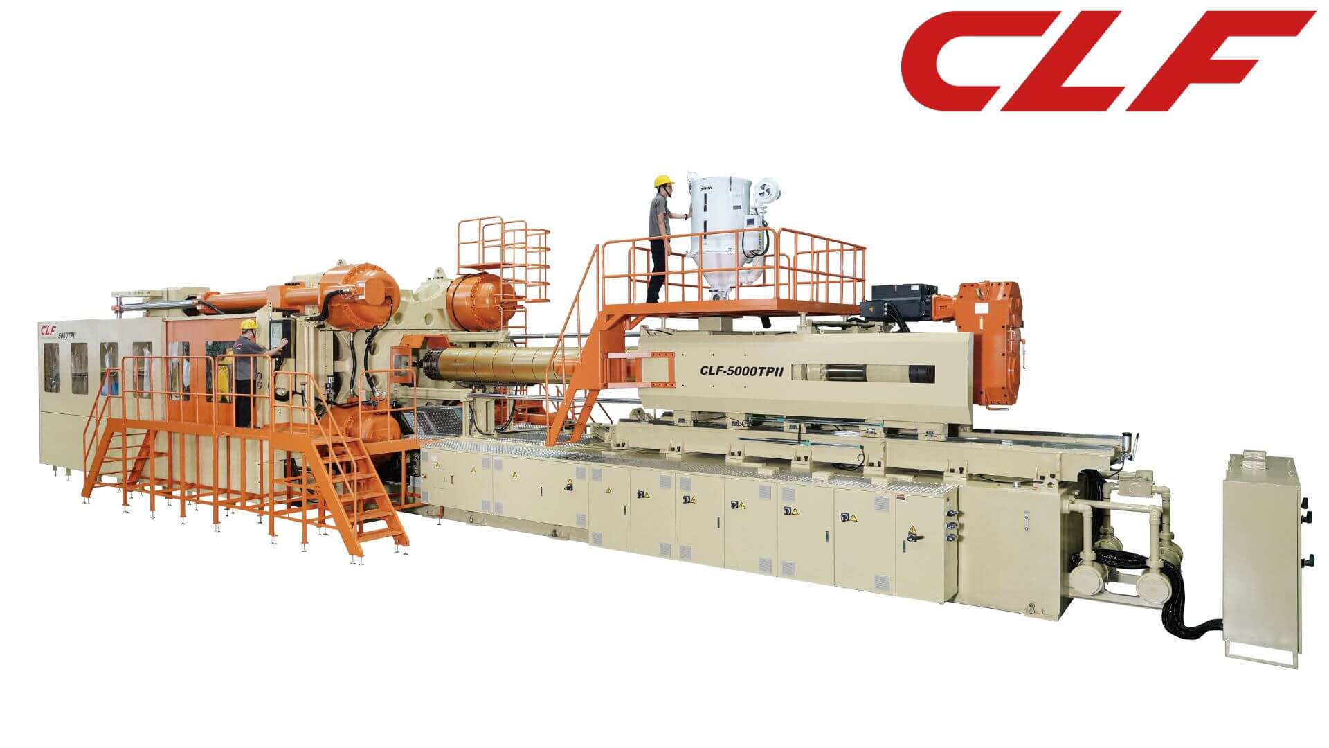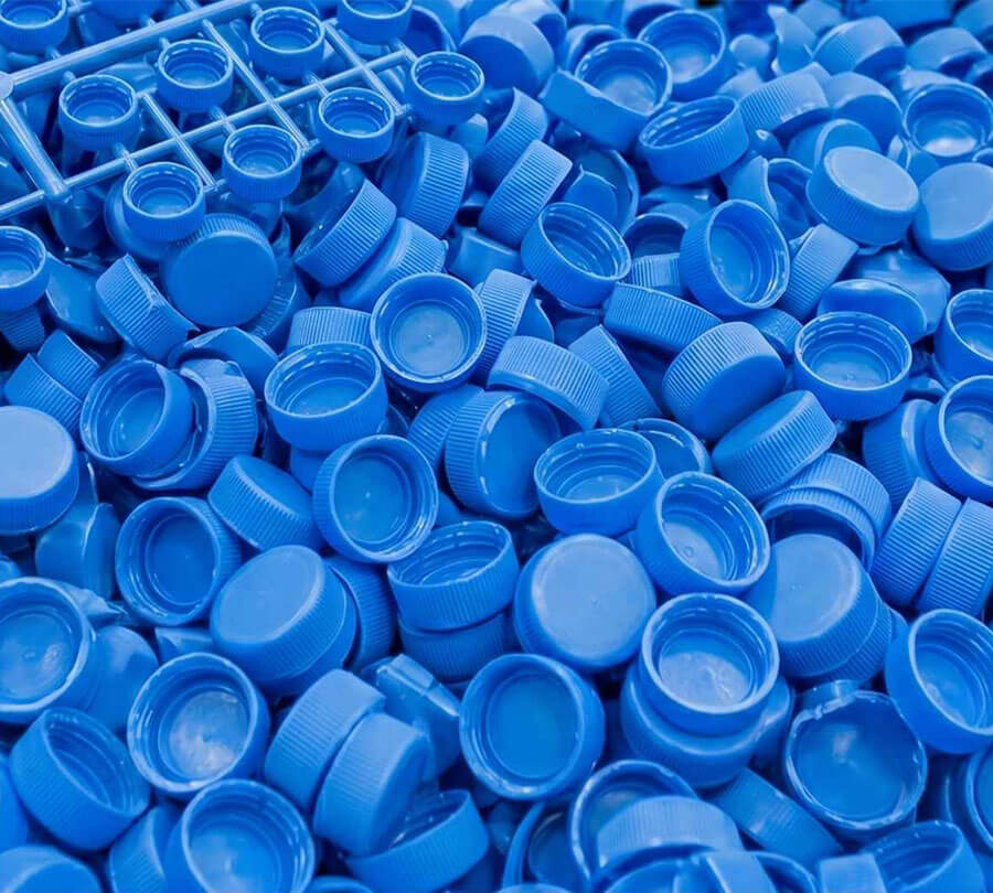

High-Speed Injection Molding Machines: Cycle Time, Thin-Wall Design, and the CLF TX Series
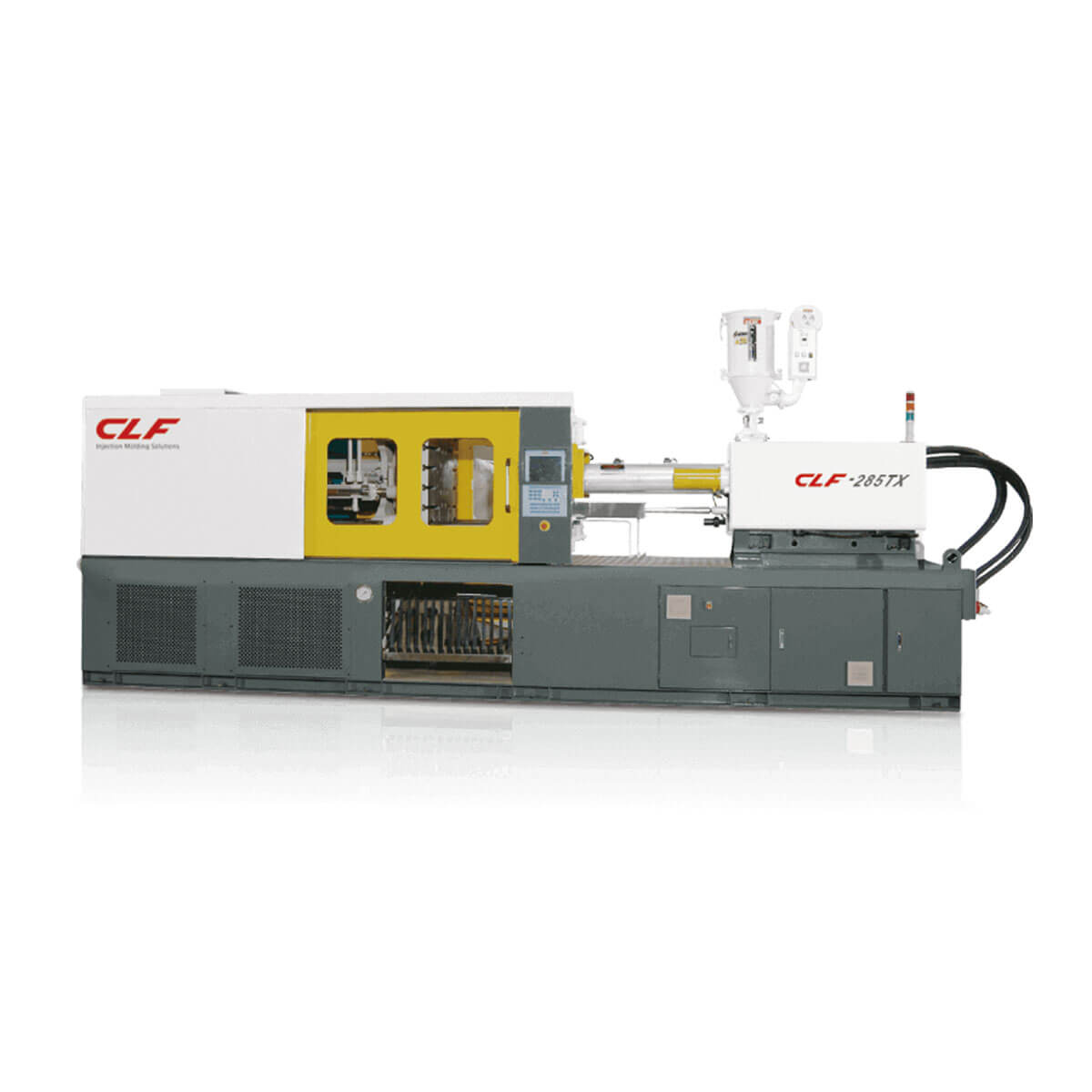
Cycle time is the number that separates a profitable high-speed packaging line from one that misses margin targets — and it is set more by machine architecture than by mold design. This guide covers the three metrics that define a high-speed injection molding machine, the structural requirements for running thin-wall parts reliably at volume, and how the CLF TX Series delivers on each of them across a 60 to 1,200-ton range.
If you are evaluating machines for thin-wall packaging, PET preform, polypropylene (PP) cap, or precision electronics production, the three sections below give you a technical framework for the purchase decision: drive architecture, the specific machine-side challenges of thin-wall molding, and a production case with verified numbers.
Three Metrics That Define a High-Speed Injection Molding Machine
"High-speed injection molding machine" has no single industry-standard definition. In practice, procurement teams use three measurable benchmarks to compare machines objectively:
- Dry cycle time: the time required to complete one full open-and-close clamp stroke with no material injected. This is a direct measure of machine kinematic performance, independent of mold design, and the clearest apples-to-apples comparison between competing platforms.
- Injection speed: the rate at which molten resin enters the cavity, expressed in mm/s. For thin-wall parts, this is non-negotiable — if melt reaches the cavity end after the frozen layer has formed, the result is a short shot.
- Shots per hour: a composite figure combining dry cycle, cooling, and plasticizing times. This is the number that converts machine specs into a production plan and justifies capital expenditure.
One common misconception needs addressing directly: "high-speed" does not mean all-electric. All-electric machines with ball-screw drives are a sound choice below 300 tons, where the precision and energy profile of that drive system are well matched to the application. Above 300 tons, the engineering changes. Ball screws sized for mid-to-large clamping forces become cost-prohibitive and wear quickly under sustained heavy-load cycling. That is the design rationale for the TX Series: a servo-hydraulic toggle architecture that delivers fast cycle times across 60 to 1,200 tons without the tonnage ceiling of all-electric configurations.
For a full comparison of hydraulic, electric, and hybrid drive systems, see CLF's technical article on selecting between hydraulic, electric, and hybrid injection molding machines.
Once the drive architecture is settled, the next question is what actually determines speed within that architecture — and the answer is cycle time, specifically the portion of it that machine design controls: the dry cycle.
How Injection Molding Cycle Time Affects Output — and Why the Dry Cycle Is the Lever
A complete injection molding cycle runs through six phases: clamp, inject, hold/cool, plasticize, open, and eject. Cooling time is largely fixed by part geometry and resin thermal properties — machines have limited influence over it. The dry cycle, by contrast, is entirely a function of machine kinematic design, and it compounds directly into output.
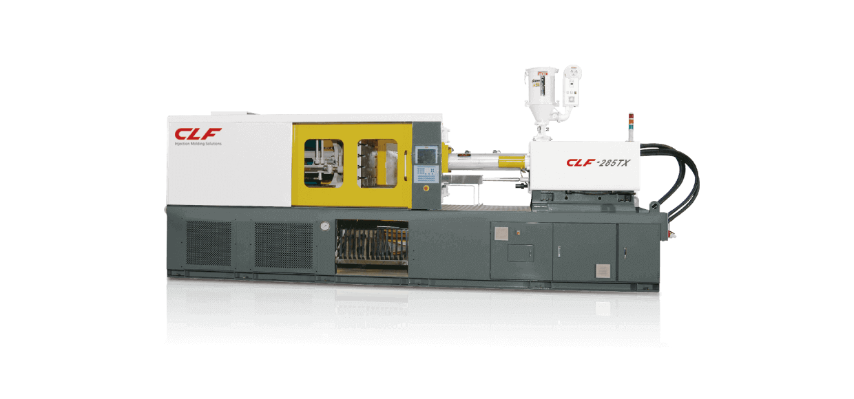
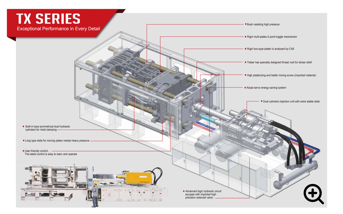
The TX Series achieves a consistent sub-2-second dry cycle (measured on the CLF-285TX in a standard thin-wall packaging configuration; actual figures vary by model, mold weight, and opening stroke) through the five-point toggle mechanism's optimized motion profile. Rather than running clamp and plasticizing as sequential operations, the TX Series runs them in parallel via a synchronized multi-circuit hydraulic system. The five-point toggle geometry allows the hydraulic cylinders to lock and release the mold in milliseconds within a short travel distance, converting mechanical efficiency directly into clamp speed.
Dry cycle savings accumulate across every cavity, every shift, every product line running on that machine. For a thin-wall packaging line, the gap between a 2-second and a 4-second dry cycle is the difference between hitting and missing throughput targets — without changing the mold, the resin, or the cooling time.
What Thin-Wall Injection Molding Actually Demands from the Machine
Thin-wall injection molding places three specific demands on the machine that standard injection setups are not designed to meet. Getting those three things right is what determines whether a high-speed line holds its tolerances at volume.
Injection Stability: Managing a Millisecond Fill Window
The fill window in a thin-wall cavity is measured in milliseconds. Once melt contacts the cold mold surface, a frozen layer begins forming immediately, reducing the effective flow cross-section and driving up injection pressure demand. Any lateral deviation in the injection axis during that window produces uneven fill and dimensional variation.
The TX Series uses a dual-cylinder injection unit with an extra-stable linear slide — a design that maintains axial precision under high-speed, high-pressure injection conditions and prevents the kind of off-axis movement that generates fill imbalance in multi-cavity thin-wall molds.
Platen Rigidity: FEA-Validated Box-Frame Construction
Thin-wall injection pressures often run two to three times higher than standard molding applications. Any platen deflection under that load — even at the micron level — produces flash and accelerates mold wear.
The TX Series fixed and moving platens use a box-frame structural design validated through finite element analysis (FEA), a computer-based structural simulation method. The FEA-validated geometry distributes clamp load uniformly across the entire mold face, keeping deformation near zero at full clamp. CLF's catalogue states this directly: "FEA-validated design keeps deformation near zero under full clamp, eliminating flash on critical thin-wall parts."
The TX Series also uses MOOG servo valves throughout the hydraulic circuit. MOOG valves are precision proportional control components — they respond to pressure commands in milliseconds and hold set-point pressure with high repeatability, which translates directly into consistent shot weight and wall thickness across a multi-million-shot production run.
Thermal Stability: Servo Energy-Saving System for Long Production Runs
Thin-wall packaging lines run at cycle counts measured in millions per month. At that frequency, hydraulic oil temperature rise becomes a precision variable: as oil heats, its viscosity changes, and the hydraulic system's response characteristics shift. The TX Series servo energy-saving system drops pump output substantially during hold, cooling, and plasticizing phases — the machine only draws full power during active clamp and injection. Oil temperature stays lower and more consistent, preserving hydraulic response accuracy across long production runs while reducing energy consumption.
For tonnage recommendations by application — food containers, electronics housings, automotive lightweight components — see CLF's thin-wall injection molding machine page.
Those three machine-side requirements — injection stability, platen rigidity, and thermal consistency — map directly onto the six structural design decisions in the TX Series described next.
CLF TX Series Architecture: Six Core Design Features
Each feature in the table below addresses a specific production challenge. All six are documented in the TX Series catalogue.
| Design Feature | Technical Description | Production Impact |
|---|---|---|
| Five-Point Toggle Mechanism | Specially tuned motion profile locks and releases the mold in milliseconds | Consistent sub-2-second dry cycles; more shots per shift |
| FEA-Validated Box-Frame Platens | Fixed and moving platens use box-frame construction, verified by CAE/FEA simulation | Near-zero deformation at full clamp; flash-free thin-wall parts |
| MOOG Servo Valves | Precision proportional control valves with millisecond pressure response | Consistent shot weight and wall thickness across long production runs |
| Diagonal Hydraulic Cylinder Layout (≥400 t models) | Built-in diagonal cylinder arrangement shortens overall machine length | Machine length reduced by up to 20%; improved floor space utilization |
| 4-3-4-3 Toggle Plate Assembly | Multi-plate linkage configuration distributes heavy clamp loads evenly | Eliminates localized mechanical stress; extends toggle service life |
| Shut-off Nozzle (customizable option) | Barrel fitted with a shut-off nozzle using a needle-valve design with short, fast closing stroke | Prevents low-viscosity material leakage; allows simultaneous plasticizing during mold opening and part ejection, effectively shortening cycle time |
The TX Series runs from the CLF-60TX through the CLF-1200TX, covering 60 to 1,200 tons with a consistent servo-hydraulic toggle architecture across the range. Screw diameters, tie-bar spacing, platen dimensions, and machine footprints for each model are available on the TX Series product page.
Production Validation: PET Preform and PP Cap Molding in Egypt
Specifications become credible when they hold up in production. A benchmark beverage and food packaging manufacturer in Egypt was running high scrap rates and dimensional instability on lightweight polyethylene terephthalate (PET) preforms and polypropylene (PP) caps — both tight-tolerance thin-wall components where minor injection deviations translate directly into dimensional failures.
Three Problems Before the TX Series
The plant faced three interconnected production issues before commissioning CLF equipment:
-
High scrap rate
: persistent injection deviations caused dimensional non-conformance on both PET preforms and PP caps, compressing material utilization. -
Long cycle times
: existing machine speed could not meet peak-season order throughput requirements. -
Inconsistent quality
: part dimensions fell short of international export standards, limiting the customer's access to export markets.
Measured Results After Commissioning the 120TX and 285TX
CLF configured two machines — the CLF-120TX and CLF-285TX — with precision servo systems and reinforced clamping mechanisms. The plant recorded three quantified improvements:
-
Scrap rate down 35%
: improved injection precision eliminated the dimensional failures that were generating rejects, with direct improvement in material utilization. -
Cycle time reduced 20%
: faster cycle throughput relieved peak-season delivery pressure. -
Export market access
: consistent part dimensions met international standards, opening export channels that had previously been out of reach.
All three outcomes trace to the same root cause: the TX Series clamping precision eliminated the injection deviations that were producing the scrap. For the full account, see the Egypt PET and PP molding case study.
Those results rest on a manufacturing foundation that is worth examining directly — because the same machine specification from two different builders does not always produce the same long-term performance.
Where Machine Precision Comes From: CLF's In-House Manufacturing
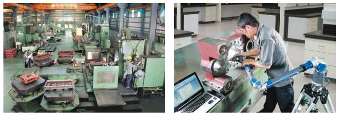
Platen dimensional accuracy is not a specification you can purchase from a component supplier — it is machined in. At CLF, all critical structural components of the TX Series, including the mold platens, are machined entirely in-house. The hole accuracy of the tie bars is also controlled in-house, per the TX Series catalogue, to ensure optimal running efficiency and part accuracy.
The production floor runs Japanese Toshiba floor-type jig boring machines and Japan Kotobuki double-column machining centers. Direct control over platen and tie-bar machining means that the dimensional relationships between those two components — the ones that determine how evenly clamp force distributes across the mold face, and how smoothly the clamp system moves under repeated high-speed cycling — are verified against specification at the point of manufacture, not after assembly.
For a machine accumulating millions of cycles per year, that manufacturing control is what separates consistent long-term performance from gradual degradation in clamp accuracy and shot repeatability.
TX Series Configuration Guide: Three Common Use Cases
The TX Series uses a consistent servo-hydraulic toggle architecture across 60 to 1,200 tons, but the priority specs shift by application. Below are the three most common use cases and what to focus on for each.
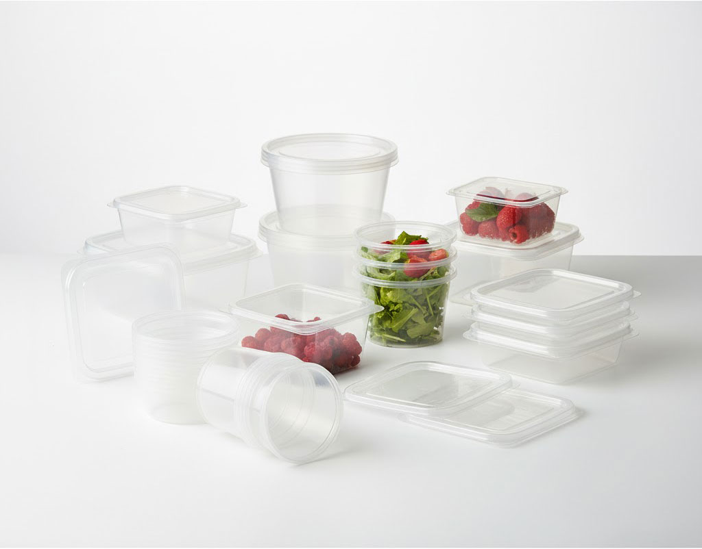
Thin-Wall Food Containers and Packaging (Including IML Lines)
The primary metrics here are dry cycle time and injection speed. TX Series models in the 100 to 230-ton range cover most food container and lid applications. For in-mold labeling (IML) production, the TX Series modular architecture supports full integration with IML label-insertion robots, part-removal robots, and conveyor systems — CLF recommends specifying IML equipment supplier and machine interface requirements at the time of inquiry so the engineering team can confirm the integration configuration.
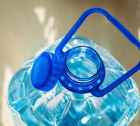
PET Preforms and PP Caps
Dimensional repeatability and consistent shot weight are the critical variables for preform and cap production. The MOOG servo valve pressure response and the FEA-validated platens' near-zero deformation under peak injection pressure are the two design features that drive scrap reduction in this application — as the Egypt case demonstrates. The 120TX and 285TX are the most common configurations for this product type; European-standard controllers and optimized mold cooling circuits are frequently specified alongside.
Electronics Housings and Precision Consumer Goods
Sub-1 mm wall thickness in electronics housings places extreme demands on melt cleanliness and injection sealing. The TX Series shut-off nozzle option (available as a customizable add-on) prevents low-viscosity material leakage and allows simultaneous plasticizing during mold opening, which is critical for parts requiring high optical clarity or tight surface finish tolerances. Models in the 150 to 350-ton range cover most electronics housing geometries.
To calculate the clamping force your specific part requires, CLF's injection molding tonnage calculation guide walks through the projected-area method with material-specific clamp factors — a useful first step before finalizing machine size.
Frequently Asked Questions
Q1 | What is the practical difference between a high-speed injection molding machine and a standard machine?
The gap comes down to three variables: dry cycle time (machine kinematic efficiency), injection speed (fill-rate capability), and shot-to-shot repeatability. Standard machines run sequential clamp and plasticizing operations; high-speed machines run them in parallel, compressing non-productive cycle time. The TX Series five-point toggle mechanism is the structural feature that delivers parallel operation and consistent sub-2-second dry cycles on the CLF platform.
Q2 | What product types is the TX Series best suited for?
Thin-wall packaging (food containers, lids, beverage caps), PET preforms, PP caps, electronics housings, and precision consumer goods — applications where wall thickness is tight, tolerances are strict, and production volume is high. For large automotive components, industrial pallets, or deep-cavity parts, CLF's TWII outward toggle series or TPII two-platen series are the appropriate platforms for those geometries.
Q3 | How do I calculate the clamping force my part requires?
The standard formula is: clamping force (tons) = projected area (cm²) × material clamp factor (kg/cm²) ÷ 1,000. Clamp factors vary by resin — lower for free-flowing materials like PP and PE, higher for viscous materials like PC and ABS. CLF's tonnage calculation guide covers the full method with material-specific factor ranges. CLF application engineers can also confirm the right tonnage from your mold dimensions and resin specification.
Q4 | Does the TX Series support IML (in-mold labeling) automation integration?
Yes. The TX Series has a modular automation architecture that supports full IML cell integration, including label-insertion robots, part-removal robots, and outfeed conveyors. Machine opening dimensions and controller interfaces can be configured to match your IML equipment supplier's specifications. Provide the IML system specs at inquiry stage so the CLF engineering team can confirm the integration package.
Q5 | How does TX Series energy consumption compare to conventional hydraulic machines?
The TX Series servo energy-saving system cuts pump output substantially during non-active phases — hold, cooling, and plasticizing — so the machine draws full power only during active clamp and injection. The servo system also keeps hydraulic oil temperature lower and more stable, which helps maintain injection precision over long production runs. Specific energy savings vary by model, production cycle, and application; CLF application engineers can provide an energy assessment for your specific configuration.
TX Series: Specifications and Technical Consultation
The TX Series covers 60 to 1,200 tons with a consistent servo-hydraulic toggle architecture — built for thin-wall packaging, PET preforms, PP caps, electronics housings, and precision consumer goods at production volume.
- Full technical specifications: screw diameters, tie-bar spacing, platen sizes, and machine footprints across the TX Series range
- Thin-wall application tonnage guide: recommended configurations by product type on the thin-wall molding machine page
- Technical consultation: contact the CLF application engineering team with your part specifications and output targets for a machine configuration recommendation.